

Bastli Circular Saw
In the Bastli, we have always been using two cheap (most probably chinese) circular saws to cut our FR4-PCBs. As a matter of fact, FR4 is an extreme abrasive material (it is principally fiberglass) and thus wore down the 5cm-HSS-sawblades very quickly, which resulted in a poor cut-quality and cutting became burning... Additionally, the saws were very weak, they always got stuck which was very annoying.So, right before the spring semester 2011, Mario Mauerer and Lukas Schrittwieser came up with the idea to build a better circular saw. It should become a much, much more powerful and durable saw...(harrharr..)
Additionally, we'd just heared the lecture on ,,power electronics'' at the ETH so we thought why not try that stuff out?!? How hard can it be?!?! (pretty tricky as it turned out ;-) )
During the spring semester, we have been developing and building that crazy thing, it took us about 15-20 weeks.
And this is what we've come up with:
Here some features of the system:
Saw:
- BLDC Motor (2kW peak (ca. 50A @ 40V))
- 10cm sawblade (coated carbide metal, 120 tooth)
- Built-in inverter (40V, ca. 50A)
- Self-built body (Aluminium, steel)
- Built-in fan for cooling
- Attached vacuum-cleaner
- 700W continuous output Power (20A @ 35V)
- Active PFC: 230V AC mains ==> 400V DC
- Forward-Converter: 400V DC ==> 35V DC
- Ca. 85% efficiency
- Two fans for cooling
The saw and the SMPS were completely built by ourselves, Mario took care of the mechanical design of the saw and the inverter while Lukas constructed the power-supply.
In the following, we will present a few details of the saw and the SMPS.
Saw
The whole idea of building a new saw came up when Mario found a big brushless motor in his basement he'd bought years ago on ebay, because that motor was well suited for such an application, it's got a lot of power and a lot of torque. It is a permanent-excitet synchronous motor that is normally used in model airplanes. But it also works in saws ;-) More details on this type of motor can be found here.(Wikipedia)Firstly, Mario's built a prototype of the inverter to test the whole commutation-stuff using the Back-EMF-Method. (Google: "Direct Back EMF Detection Shao", "Microchip AN857", "Microchip AN885" etc.)
Then, we had to find out whether our BLDC had enough power to drive a 10cm blade. Therefore, we've built a "torture rack" for the BLDC:
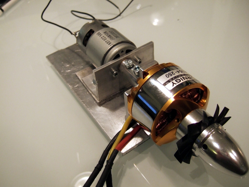
The BLDC was attached to a brushed-type DC motor. The DC-motor was used as a generator and thus put some load onto the BLDC. It was soon clear that it was a walk in the park for the BLDC to turn the DC-motor into a little smoke-machine, it had no problems at all when it was running at 300W (we couldn't get more from our laboratory supply). It also has enough torque to destory a little village. The inverter didn't even get warm...
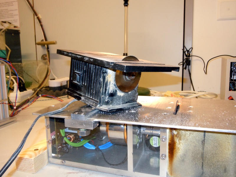
As soon as we knew that the BLDC has enough power, Mario began building the enclosure for the motor in his shed:
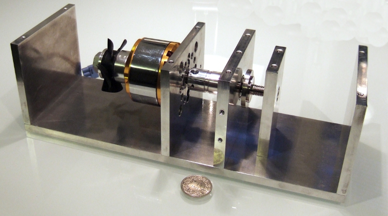
The motor has a PC-fan mounted on it to move the air around a bit, maybe this helps cooling the motor.
The saw blade is attached on a V2A stainless-steel axle:

Meanwhile, Mario has also built the inverter. The inverter shall create a rotating field in the motor. This is achieved with this circuitry: Three-Phase-Inverter
MOSFETs are used as switches and an AtMega88 controls the motor (simple PI-controller) and supervises some system parameters (voltage, temperature, current etc.)
The input voltage of the inverter is 35V.
And after a few weeks, everything came together:

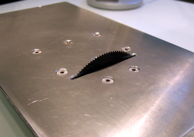
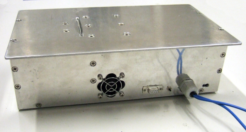
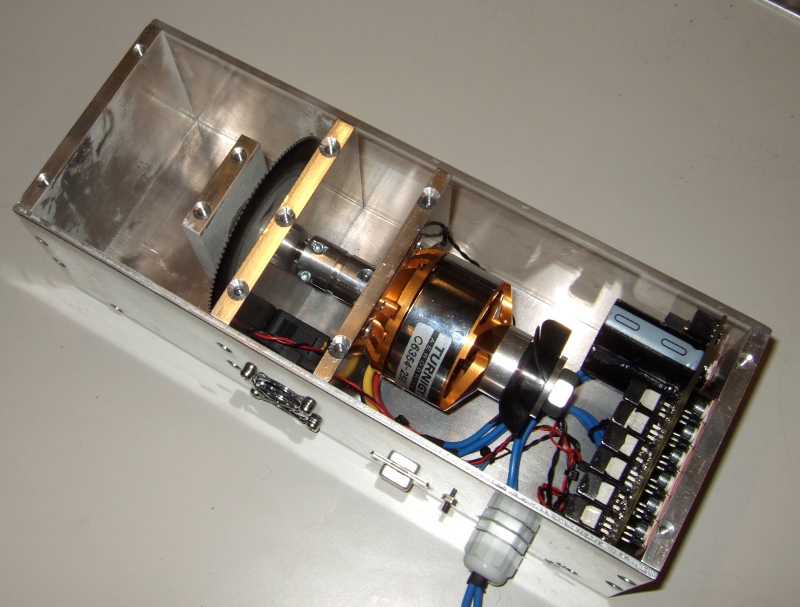
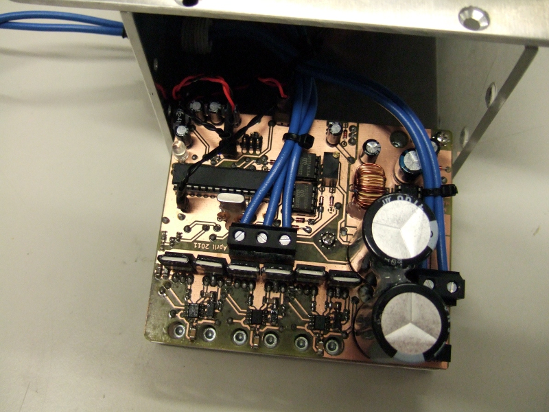
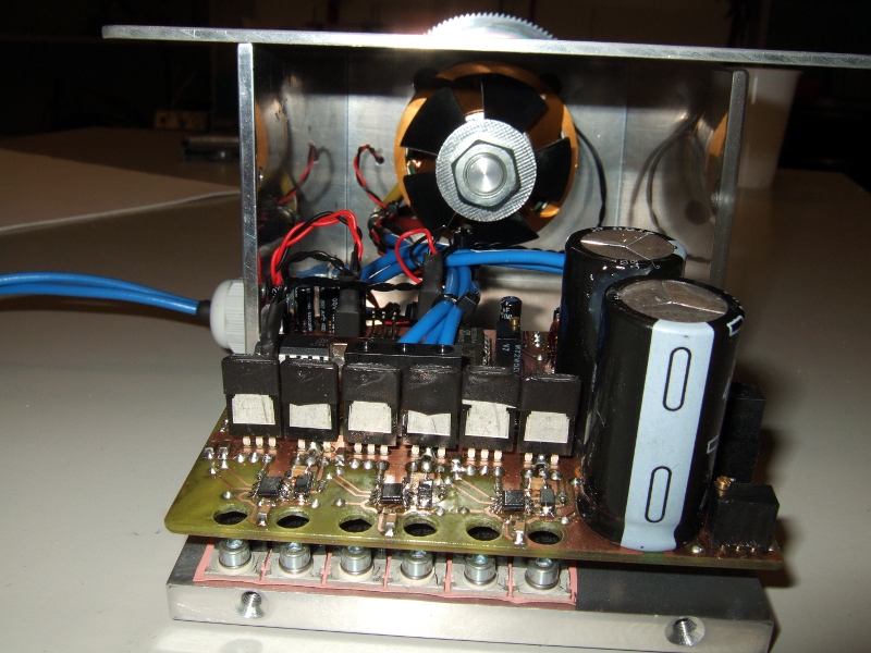
The inverter has even found a place in the saw itself. A 40mm PC-fan tries to shove some air through the motor to cool it down when it gets too hot (it's got a temperature sensor). The inverter has a RS232- terminal to be able to communicate with the outside world. A ,,boost-button" at the back powers the saw to full speed for ca. 30s. A poti (also at the back) allows to adjust the rpm.
The inverter lets the motor beep three times as a warning sign before starting it up.(see Video below) This beeping also positions the rotor in a defined way so that it is easier to start the synchronous motor.
The schematics (Kicad) and software for the inverter can be downloaded here: inverterdata.zip (7MB)
Power Supply
Whilst Mario was building the saw, Lukas developed the 700W SMPS. We found that 700W would be a nice power for the saw and the motor. Actually, 300W would have been enough, but 700W are more fun (and because we can) :-)Both, the PFC and the Forward Converter where designed on paper and simulated using GeckoCIRCUITS, a circuit simulator designed special for power electronics. The simulations where used to test and tune the controllers of both converters. You can find screenshots of the simulations here: PFC, Forward
This SMPS runs with the same technology as a standard computer power-supply. It actually consists of two converters, an active-pfc circuitry and a forward-converter.
The active-PFC makes sure that the current is drawn from the mains is sinusoidal and thus, the supply has a nearly perfect power-factor (ca. 0.98-0.99) and doesn't create harmonics in the mains.
Lukas used a slightly modified version of this simple, yet effective circuitry: A robust digital PFC control method suitable for low-cost microcontrollers(PDF)
The basic idea is to use a boost converter to create a 400V DC output from the rectified sine input. However the converter needs a special control so its input current becomes sinusoidal and in phase with the mains voltage. The solution from the paper mentioned above uses a shunt resistor to measure the coil current of the boost. This current is compared with a sinusoidal reference which is direved directly from the rectified mains. An additional ATTiny26 microcontroller controls the current amplitude to achive a constant DC output voltage. To keep the switching noise on the mains to a minimum a filter was added (we directly took the L- and C-components from a UPS-SMPS). All power components used in PFC were recycled from used PC and server power supplies, this kept the expenses low :-)
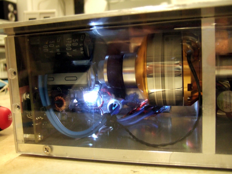
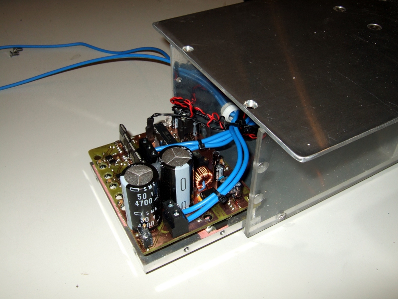
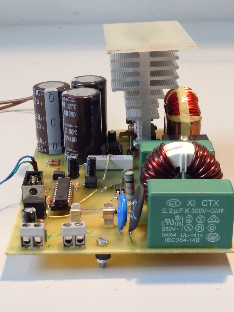
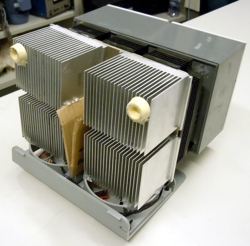
Here are two pics of the PFC. You can see the bulky capacitors for the 400V link, the heatsink which cools all the power semiconductors (mains rectifier, mosfet and output diode). The filter is in the far right corner (the big green capacitors and the coil), in front of it is the microcontroller and the comparator. On the second picture you can see the boost converts coil too.

After the active-PFC, an isolated converter is needed because the supply should have a galvanic isolation due to security reasons. (nobody likes 400V with power behind it on a touchable surface....) The choice fell on a two-switch forward converter. Your can find documentation about forward converters here: ETH lecture notes, german, PDF or at: Wikipedia
Basically it's a boost converter with an additional transformer after the mosfet for the galvanic isolation. Again many parts from old PC-power supplies from the junkyard where reused. Luckily, we've even found a suitable transformer core in our lab. Although we did simulations and we tried to be as carefull as possible some mosfets and diodes blew up. It turned out that there is a little bit more behind the naked theory that wants to be taken care of :-) In real life, for example, a diode is not an ideal switch. There is always some reverse recovery current which has to be taken care of. Even for the output schottky diodes a snubber network was necessary due to the transformer's stray inductance (snubber dimensioning is purely black magic!) and many other tricks to get that thing running (filters, HF-braid for the transformer because of the skin effect which is visible at 100kHz switching frequency , etc.) Most of the mosfets died very quietly, just a small click and the fuse blows. However there were some spectacular blowups. At a test run the two transformer core halves moved a little bit which lowered the transformers magnetizing inductance and led to overstressing of the freewheeling diodes. When the diodes died they became a pretty good short circuit which in turn led to disintegration of the mosfet tring to short the DC link capacitor charged to 400V. So Mario tried to weld the two ferrite E-cores of the transformer together using a welding-laser to reduce the stray-inductance. (didn't work, ferrite is too brittle, it just breaks some chips off due to the large heat from the laser). Another big problem was EMI. The large switching noise made it very hard to do any useful measurement on the converters. This created very unstable controller behavior in the forward converter. The solution was to us a faster ADC to do the measurements between two switching operations.
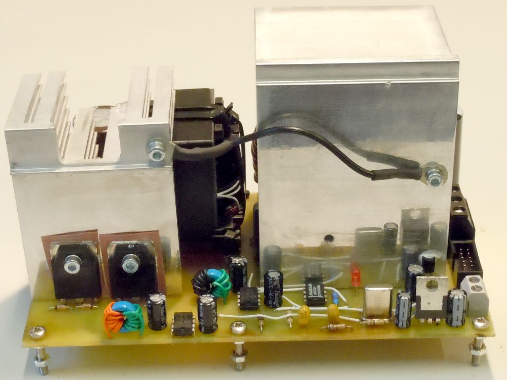
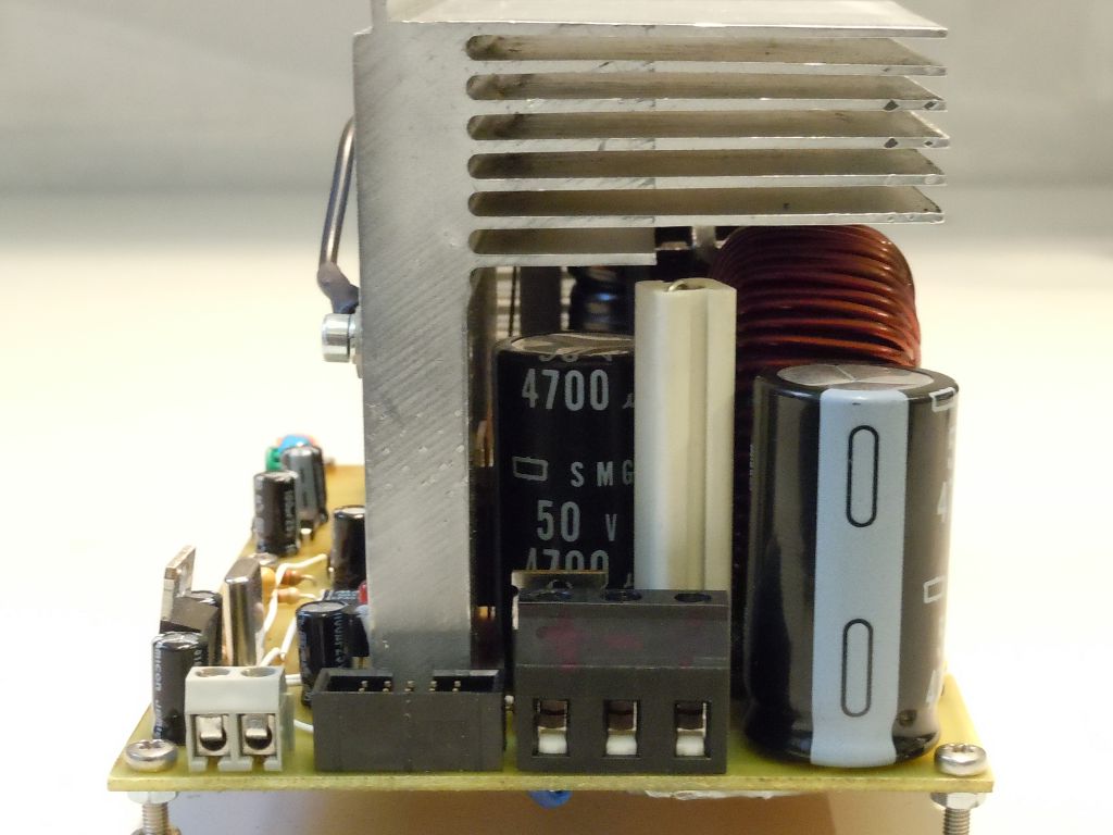
These two pictures show the forward-converter.
For testing, we had to put some well controllable load on the supply. Firstly, Lukas used a bunch of lightbulbs. This method was usable for the 400VDC as well as the 35VDC. But, it was not very "controllable", these lightbulbs always want the same power...
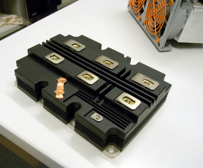
So, we've built a current sink. That is basically an adjustable resistor that converts electrical power into heat. First we tried Marios's old current sink which used an IGBT from an elevator. However for some reason it did not like the 400V DC and simply died. So another IGBT was necessary. Lukily we got a fairly big one as a present from ABB. Se we equipped Mario's old current sink with this large IGBT that is operated in linear mode. :-D (These IGBTs are normally used in trains...)
The current through the IGBT is controlled via a shunt and some OpAmps that directly drive the IGBT's gate. This works pretty well, the IGBT is our "adjustable resistor". We've even equipped the OpAmp-circuitry with an external control-input, so that we could use a function generator to pulse the load and see how the supply regulates. The following pictures show the IGBT and the current sink:
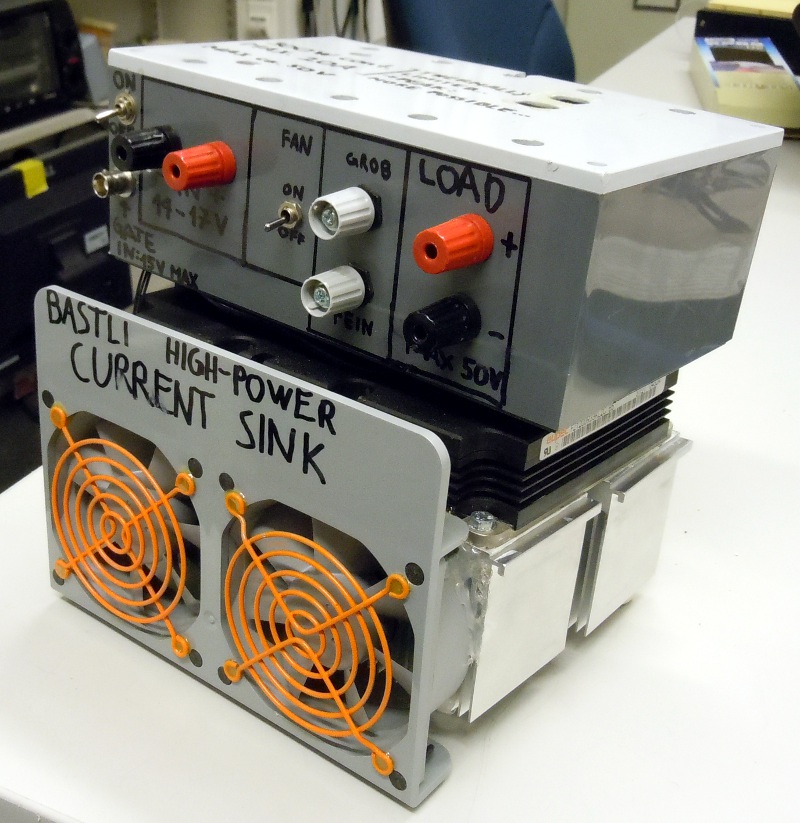
We've attached 4 Pentium-4 coolers to the IGBT and two Apple-G5-Fans that shove a lot of air (and noise) through the coolers. This is enough to dissipate 700W (continuous!). The hot-glue doesn't even melt, although this thing converts into a hairdryer :-)
The following pictures shows Lukas' test-environment:
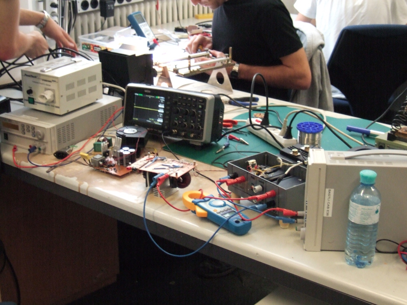
On the left, you can see the active-pfc-prototoype. The forward-converter is the PCB on the right. The current-sink is still in an older configuration.
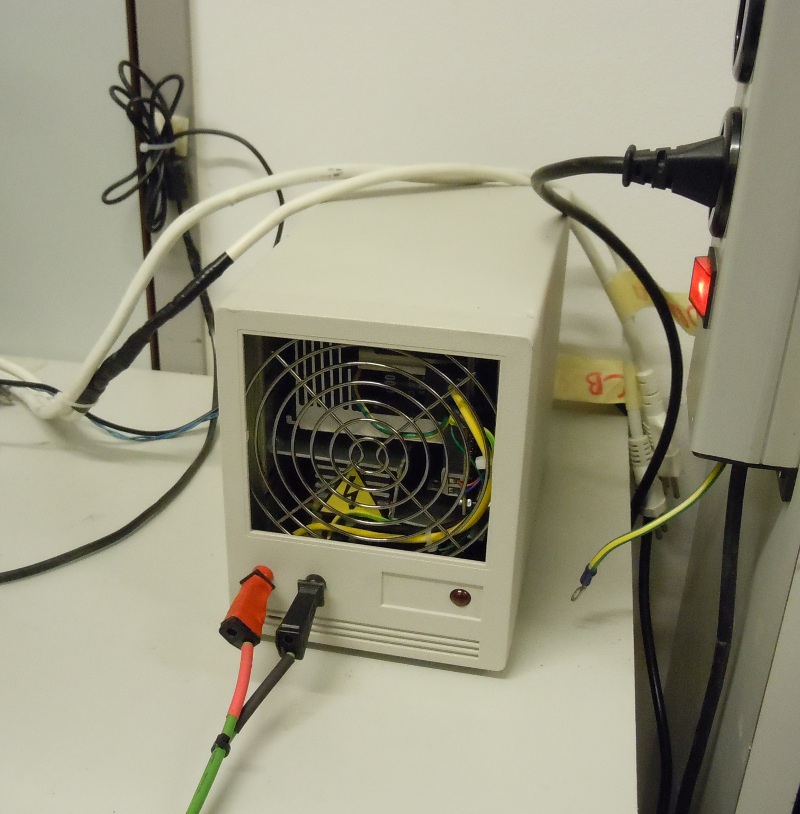
Using the current-sink and some knowhow, Lukas has eventually figured out how to run the two converters and we had to think about where to mount the two PCBs (one for the active-PFC, one for the forward). We've found an old HDD-box we wanted to fill with the SMPS. It was clear that there was very little room left in that box, so Mario has even milled custom-made coolers so that everything fits in there...And cooling is very important! When the supply has an output power of 700W and an efficiency of 0.85, it produces 105W of heat that has to be dissipated. Therefore, the HDD-box has two fans. Additionally, two small, conventional 12V-transformers (supply for the 700W-supply) also had do be crammed in that box!
When the two final versions of the converters (active-pfc and forward) were mounted in that box, they didn't work anymore...the noise from the active-pfc jammed the measurements of the forward and thus made it impossible to control that thing. But some shielding and lowering of the switching-times brought the desired effects.
The following picture shows the power supply. The upper circuitry is the forward converter, the active-pfc sits below. (high-voltage-warning-symbol). You can also see the shielding-PCB between the two coolers.
The active-pfc and the forward-converter are controlled using an AtTiny 26 each. The active-pfc has a simple PI-controller while the forward-converter has two PI-control-loops: A fast inner current-control-loop and a slower, outer voltage-control-loop. This lets the forward-converter behave like a laboratory-supply with a current limit! It just lowers the voltage when the output current gets too high!
We've learned a lot when developing this system, especially the two converters were a bit tricky and needed a lot of development-effort. But all went well and the power-supply drives the hell out of the saw :-D
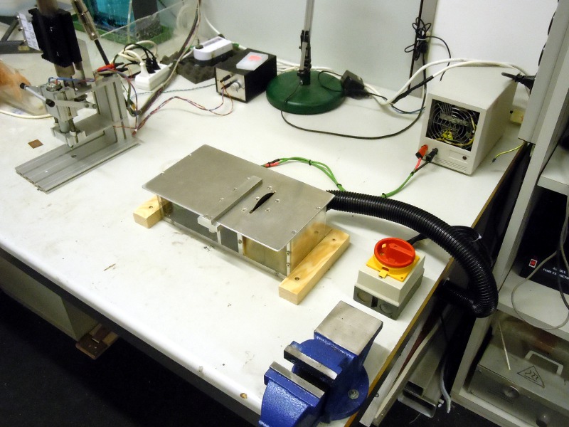
Final System
The following pictures show the system in it's final configuration.
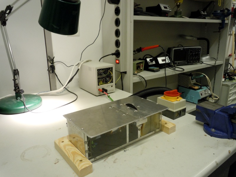
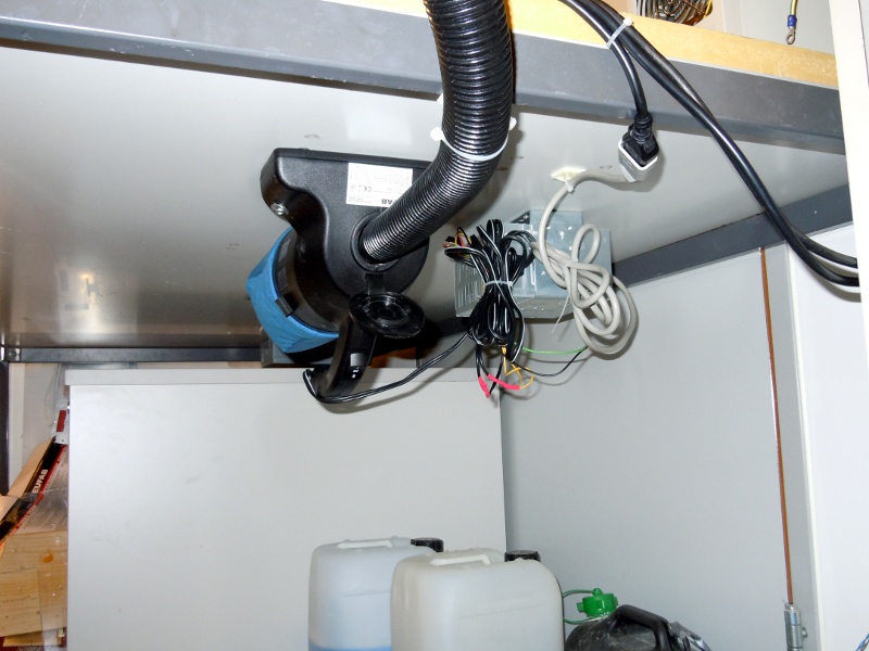
We have also attached a car-vacuum-cleaner (named "Turbo-Tiger" xD) to the saw, this sucks off all the dust. The hoover is mounted beneath the table (that was not so easy for Mario ;-) and is powered from a PC-powersupply:

The big red switch is the mains switch and it engages the 700W-SMPS as well as the hoover.
The wooden frame prevents the saw from slipping around when cutting really large pieces like a 1m x 1m x 3mm Aluminium-sheet... ;-)
The following picture is a before...after picture. We've been cutting PCBs with that old thing for ages! A wonder nobody's ever cut his fingers off, although that thing let some blood flow from time to time....
The following video shows the power of the saw and the power-supply :-D